Running DER Simulations
The DER Simulator can emulate one or more identical SunSpec Modbus devices, but it also has the ability to represent a dynamic DER device connected to a power system. The simulation environment can also simulate DC simulators, AC simulators, Data Acquisition Systems (DAS), and battery simulators–primarily for demonstrating the operations of the LabTest to work with lab hardware.
DER Simulator Description
The DER simulator runs a simulated DER device with multiple communication interfaces. This simulator can be used for development or to learn how to use other features such as scripting and lab automation.
User Interface
The DER simulator user interface is shown below.
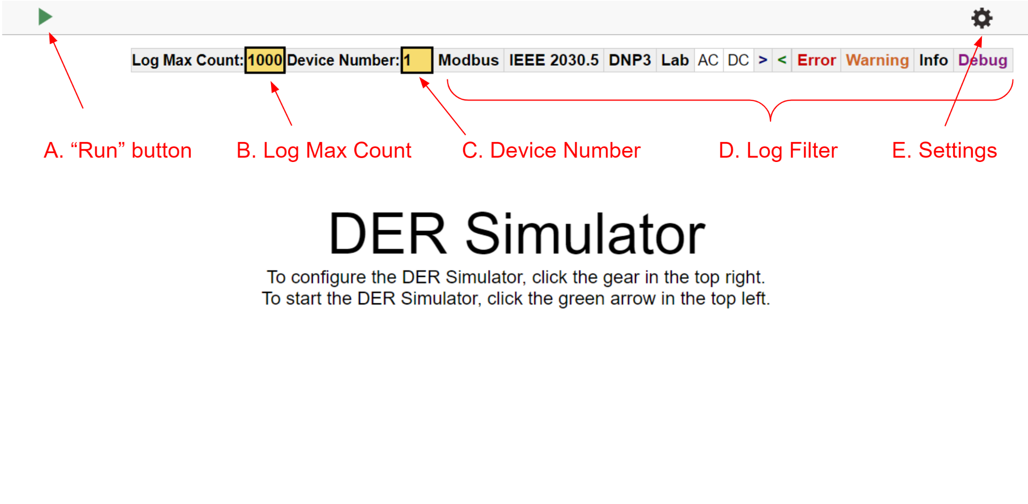
- A. “Run” Button: Starts/Stops the simulation with the current settings.
- B. Log Max Count: The log view will show at most this amount of the most recent log entries.
- C. Device Number: To filter the logs by devices. To show logs only for device 1 then input
1in device number, to show logs for devices 1, 2 and 3 then input1-3in device number. - D. Log Filter: To filter the log by level or module. The log can be filtered by the levels:
- Protocol Information: IEEE 2030.5, DNP3, and SunSpec Modbus:
>: Modbus Incoming messages<: Modbus Outgoing messages
- Laboratory Hardware Simulation threads: AC grid simulation, DC input simulation, DAS simulation, and Battery simulation
- DER Simulator thread: AC simulation, DC Simulation
- Message level: ”Error”, ”Warnings”, ”Info”, ”Debug”
- Protocol Information: IEEE 2030.5, DNP3, and SunSpec Modbus:
- E. Settings: Click to open the settings dialog where the similar settings can be changed.
Settings
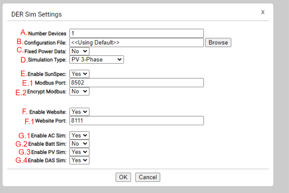
- A. Number Devices: The number of devices to simulate
- B. Configuration File: A JSON device file with the configuration of the simulated models.
- C. Fixed Power Data: Whether to use a CSV with recorded data for simulation or simulate power dynamically.
- D. Simulation Type: Number of phases of the simulated device.
- E. Enable SunSpec: Whether to enable SunSpec Modbus interface.
- E.1. Modbus Port: Port of the Modbus server
- E.2. Encrypt Modbus: Whether to encrypt the Modbus communications.
- F. Enable Website: Whether to enable the simulator’s dashboard.
- F.1. Website Port: Port for the dashboard page.
-
G. Simulated Lab Devices: Whether to simulate the corresponding device.
- G.1 Enable AC Sim: The AC Sim emulates an Ametek RS90
- G.2. Enable Batt Sim: The Batt Sim emulates an NHR 9200
- G.3. Enable PV Sim: The PV Sim emulates a Ametek TerraSAS
- G.4. Enable DAS Sim: The DAS Sim emulates a Yokogawa WT3000
-
To activate Encrypt Modbus, Click Yes, you will see << Using Default >> Certs and click OK
