Fuel Cell
DERSim ships a fuel cell device that covers both common chemistries and both common operating modes. Pick the combination with three flags:
| Flag | Choices | Default |
|---|---|---|
--fuelcell_chemistry |
PEMFC, SOFC |
PEMFC |
--fuelcell_mode |
fc_only, bidirectional |
fc_only |
--fuelcell_fuel |
tank, continuous |
tank |
The bundled reference machines cover four of the eight combinations — the rest are not real products (e.g. SOFC FC-only on a finite tank makes no sense at lab scale):
| Chemistry | Mode | Fuel | Reference machine |
|---|---|---|---|
| PEMFC | fc_only |
tank |
PEMFC-FC-only 5 kW (Ballard FCgen-LCS class) |
| PEMFC | bidirectional |
tank |
PEMFC-reversible 5 kW (FC + SOEC branches) |
| SOFC | bidirectional |
tank |
SOFC-reversible 200 kW (SOEC electrolyser branch) |
| SOFC | fc_only |
continuous |
SOFC-200kW-pipeline (natural-gas feed, no tank state) |
Start a fuel cell with the matching combination:
./sim --device_type Fuelcell-3Phase --fuelcell_chemistry PEMFC --fuelcell_mode fc_only
./sim --device_type Fuelcell-3Phase --fuelcell_chemistry PEMFC --fuelcell_mode bidirectional
./sim --device_type Fuelcell-3Phase --fuelcell_chemistry SOFC --fuelcell_mode bidirectional
./sim --device_type Fuelcell-3Phase --fuelcell_chemistry SOFC --fuelcell_mode fc_only --fuelcell_fuel continuous
If you pick an unsupported combination DERSim fails at startup with a clear error listing the four supported tuples.
What's simulated
The DC-side fuel cell model owns the full FC/EL stack plus the electrochemistry of the fuel reservoir:
- Stack polarisation curve — open-circuit voltage minus activation, ohmic, and concentration overpotentials. PEMFC and SOFC have different default coefficient sets.
- Operating-mode dispatch — FC mode (positive setpoint) draws
H₂ from the tank and produces electrical power; EL mode (negative
setpoint, bidirectional only) consumes power and refills the tank.
Idle (
mode == "idle") sits below a tiny floor power. - Ramp limits + dwell — switching between FC and EL respects a mode-change dwell to prevent thrashing; ramp rate clamps the effective setpoint each tick.
- Tank dynamics —
tankfuel supply maintains a finite H₂ reservoir that drains during FC and refills during EL.continuousfuel supply ignores tank state (the simulator reports tank fields asnullover REST and as—on the dashboard). - Stack temperature — first-order thermal model. SOFC sits near ~750 °C, PEMFC near ~65 °C; setpoint changes deflect temperature with a slow thermal time constant.
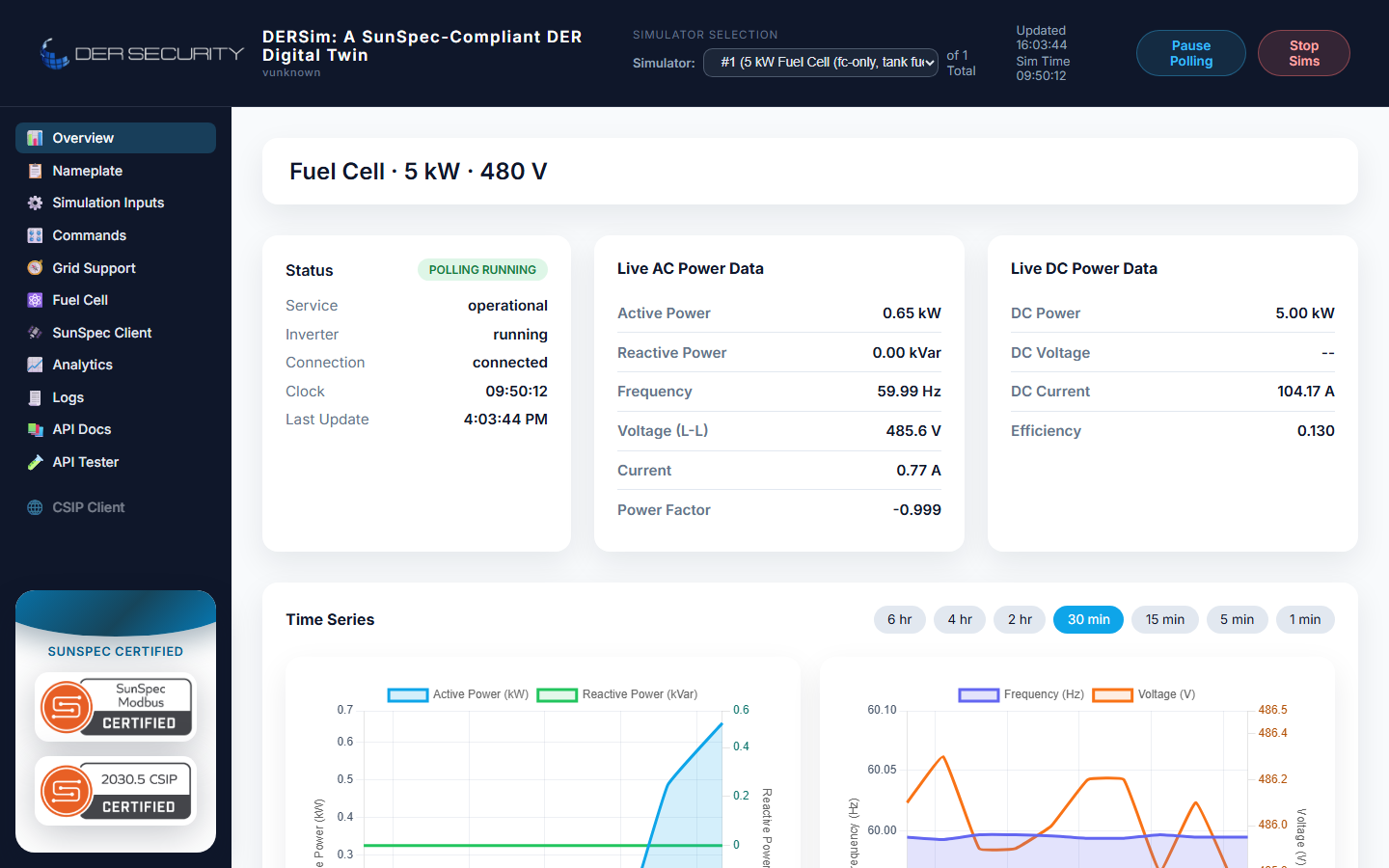
The grid-side AC output rides on top of this DC source exactly as it does for the PV inverter — every grid-support mode (Volt-Var, frequency-droop, fixed PF) applies on top of the fuel-cell-allowed active power.
Dashboard
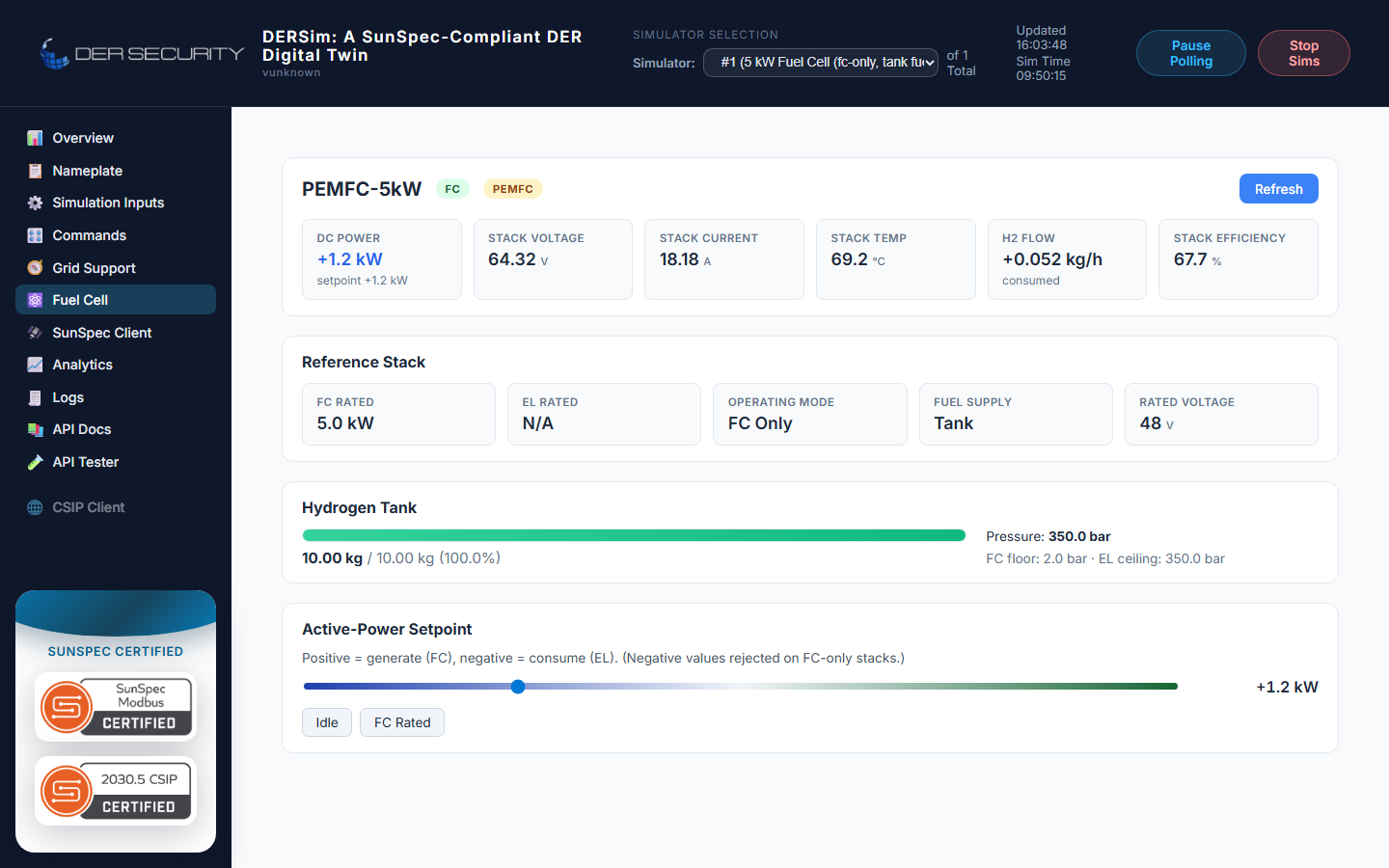
The dashboard exposes a Fuel Cell panel (sidebar 🔋) with the reference-machine identifier, active mode chip, live DC telemetry, stack temperature, H₂ flow, stack efficiency, and an active-power setpoint slider:
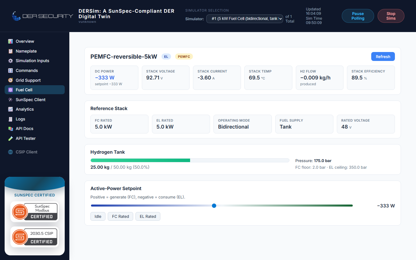
The reversible PEMFC adds the EL branch — the same panel shows the electrolyser quick-pick and accepts negative setpoints:
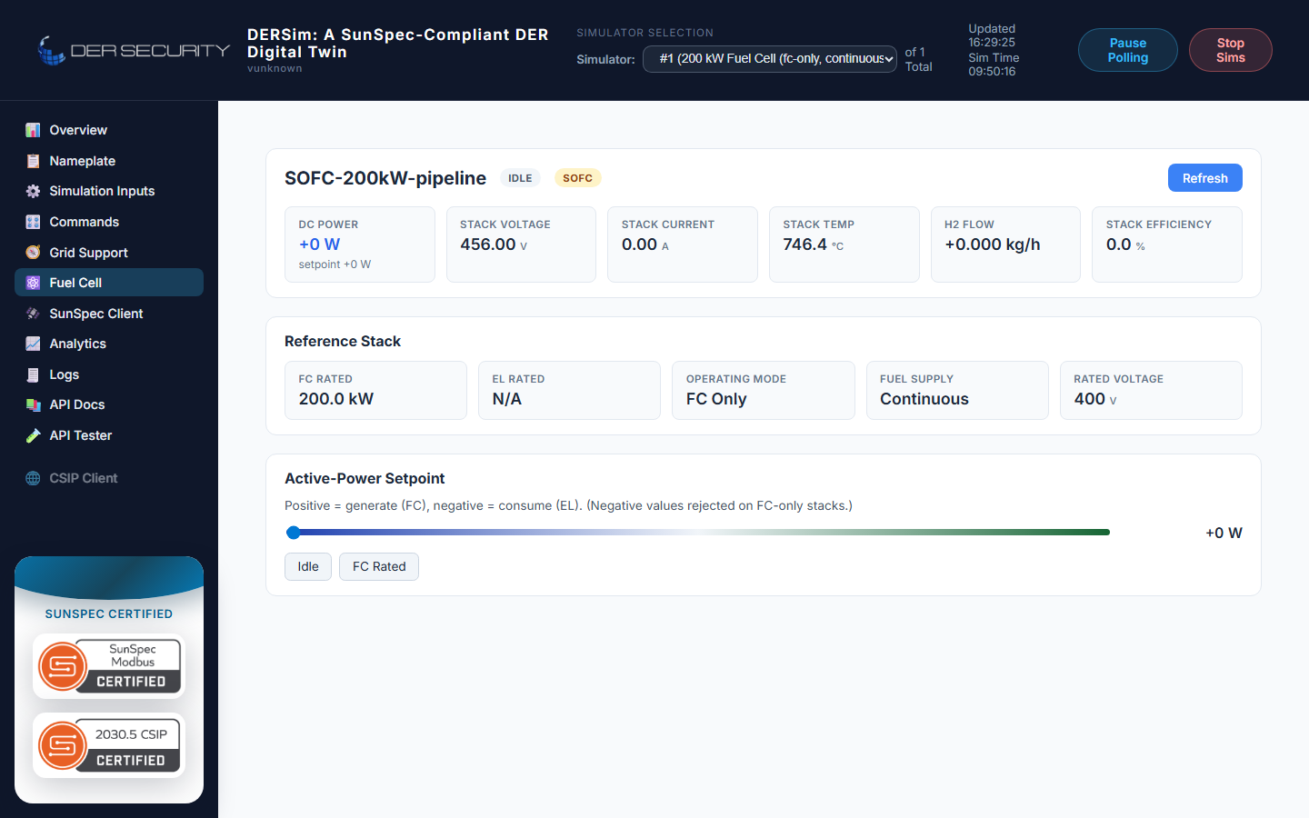
The SOFC variant on continuous (pipeline) fuel supply reports the
same operating-point fields but the tank state is blank (—) — the
panel labels the supply as "Continuous":
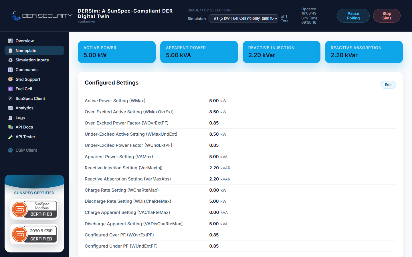
For the PEMFC FC-only scenario the nameplate and overview pages mirror the inverter chrome with fuel-cell-specific rated values:
REST control — setting the active-power setpoint
Operator-driven active power is sent as a single signed value via the setpoint endpoint:
POST /api/dersim/fuelcell/setpoint
Content-Type: application/json

{"setpoint_w": 4000.0}
- Positive values place the stack in FC mode (generating).
- Negative values place a bidirectional stack in EL mode (consuming
- refilling the tank). FC-only stacks reject negative setpoints with HTTP 400.
- Magnitudes saturate to the rated FC / EL bounds.
- Values below a small floor snap to idle (the stack stops drawing fuel).
- The setpoint is ramp-limited and clamped against the
mode-switch dwell; the live
setpoint_wfield in the snapshot is the post-ramp effective value, not the requested raw value.
The same JSON shape is what the dashboard slider posts on every operator drag.
SunSpec model exposure
The fuel cell device populates the same general DER SunSpec model set as PV (701 nameplate + live AC measurements, 702 ratings, 703 enter-service, 704 fixed PF, 705 Volt-Var, 706 Volt-Watt, 711 Frequency-Droop, 712 Watt-Var), plus the fuel-cell-relevant DC-side models:
| Model | Purpose | Key points |
|---|---|---|
714 |
DC-side input | Reads as a single port with PrtTyp = 3 (INJ, one-way FC) or PrtTyp = 5 (BIDIR, reversible). The dispatcher inspects the loaded SunSpec config and the --fuelcell_mode flag to pick the right branch. |
715 |
DC port detail | DC voltage, current, energy in/out per port — mirrors what /api/dersim/fuelcell returns. |
802 |
Battery bank | Not populated — fuel cells are not electrochemical storage in the SunSpec sense. |
The Modbus client treats the fuel cell as a SunSpec inverter with extra 714/715 telemetry on top; existing scan tools (pysunspec2, certification harnesses) work without changes.
Bidirectional mode operations
Bidirectional stacks expose the EL branch in addition to the FC branch. A handful of operational notes that aren't obvious from the dashboard:
- EL-mode efficiency is reported as a generation-equivalent number for consistency with FC-mode efficiency; for actual EL energy efficiency divide produced H₂ enthalpy by consumed electrical energy.
- Mode transitions dwell briefly between FC and EL — the dwell time prevents the slider from causing rapid oscillation between the two branches and matches typical reversible-stack control hardware.
- Tank state during EL mode counts the produced H₂ back into the tank, so a tank-supply reversible PEMFC can act as round-trip storage if the EL-mode duty cycle exceeds the FC-mode duty cycle.
Why both chemistries
PEMFC and SOFC behave very differently at the system level:
- PEMFC runs at low temperature (~65 °C), starts cold quickly, but needs pure H₂ and a humidified membrane. Lab tests for residential / vehicle-scale 5 kW class.
- SOFC runs at high temperature (~750 °C), can reform natural
gas internally (hence the
continuousfuel supply option), but takes hours to warm up from cold. Lab tests for stationary utility-scale 200 kW class.
Both chemistries respond to the same /fuelcell/setpoint REST shape
and behave the same way under grid-support modes — the difference is
in the polarisation-curve coefficients, the rated efficiency, and
the tank-supply constraint matrix.