Battery Storage
DERSim's battery device type simulates a full battery hierarchy — bank → strings → modules → cells — riding behind a SunSpec-compliant DC interface that matches what real battery management systems expose to upstream EMSs.
./sim --device_type Batt-3Phase
./sim --device_type Batt-2Phase
./sim --device_type Batt-1Phase
The phase variant only affects the AC-side inverter wire shape; the DC-side hierarchy is identical. By default the simulator sizes the battery at 15 kWh, 50% SoC, 2 strings × 4 modules × 16 cells (128 cells total) of NMC chemistry, with a 10 kW power rating. Each cell starts in a populated state with thermal and voltage spread that drifts realistically as the bank cycles.
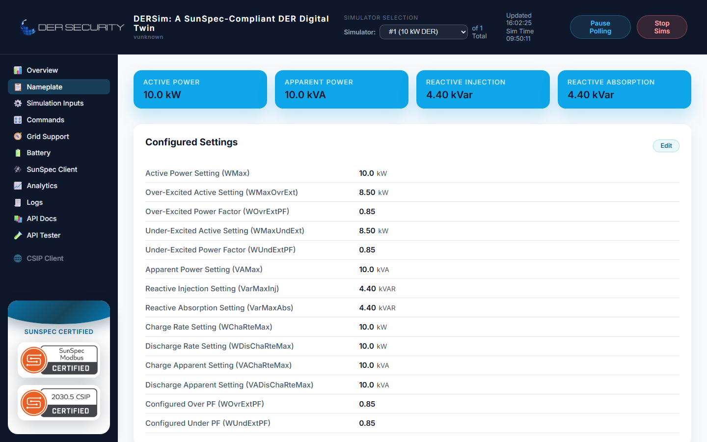
The dashboard's nameplate page surfaces the same kW / kVAR / voltage details every device type ships:
What's simulated
The DC-side battery model owns the electrochemistry, the BMS behavior, and the hierarchical telemetry that real packs expose over their CAN / Modbus / 2030.5 interfaces:
- Per-cell voltage and temperature — every cell has its own voltage, temperature, and (when the BMS triggers) balancing flag. Cell-to-cell spread grows realistically with cycling.
- String-level aggregation — each string sums its modules' voltage, averages the cell voltages, and tracks its own SoC and SoH. Contactor state per string lets you simulate string disconnection (e.g. for safety isolation tests).
- Module-level rollups — module SoC / SoH / voltage / max cell voltage / min cell voltage / temperature spread per module.
- Chemistry detection — DERSim infers NMC / LFP / Lead-Acid /
NaS / ZnBr / Li-Ion from the SunSpec model 802
Typfield. The detected chemistry is reported in the snapshot and shows in the dashboard's bank header. - Charge / discharge dynamics — ramp rate clamps and SoC ceiling / floor inhibit walk-through to overcharge or over-discharge. SoH degrades slowly with full cycles.
- State-of-Health (SoH) — bank, string, and module SoH percent the BMS would report.
Model 800-series hierarchy
The SunSpec models 800-series carry the hierarchy onto the wire in matching layers. DERSim implements all four:
| SunSpec model | Cardinality | Fields surfaced |
|---|---|---|
| 802 Battery Bank Information | One per bank | Chemistry, n_strings, n_strings_connected, total_cells, SoC, SoH, voltage, current, power, energy capacity, cell V max/min/avg, module temp max/min/avg, cycle count, EVT1 alarms |
| 803 Battery String Information | One per string in the bank | enabled, contactor_closed, SoC, SoH, current, voltage, cell extremes |
| 804 Battery Module Information | One per module per string | n_cells, SoC, SoH, voltage, cell V extremes, cell T extremes, balance count, serial number |
| 804 Per-cell extension | One per cell per module | voltage, temperature, is_balancing |
The hierarchy is strictly nested — 802 → 803 → 804 → per-cell —
matching what a real battery management system reports over its own
CAN / Modbus interface.
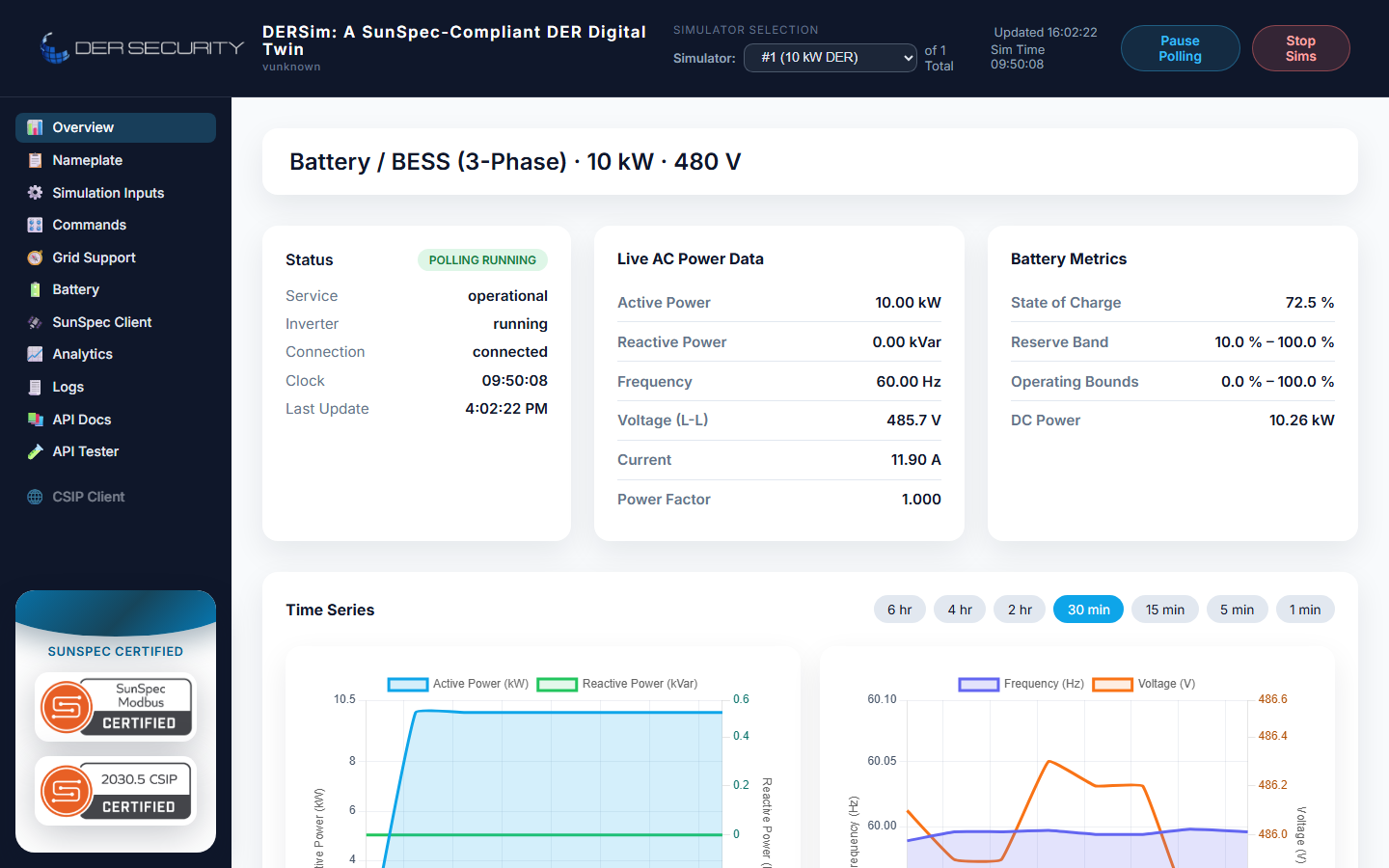
The dashboard's Battery view renders this hierarchy directly: bank metrics as a stat tile row at top, then a string table, then expandable module rows that reveal per-cell voltage / temperature.
The overview page shows the bank-level rollup — SoC, AC delivery, DC power, reserve-band tile — alongside the standard live-AC metrics every device type renders:
REST control — pinning SoC
For deterministic lab runs that need to replay a specific battery state, set the SoC directly via the controls endpoint:
POST /api/dersim/controls/battery
Content-Type: application/json

{"soc_pct": 72.5}
The value is clamped server-side to [SoCMin, SoCMax] from the
SunSpec configuration (typically 0 / 100), and the next dispatcher
tick walks the per-cell state to match. The endpoint returns the
refreshed BatteryBankSnapshot so you can confirm the value landed.
The schema also reserves soh_pct and per-cell fields for future
expansion — currently only soc_pct is accepted. The server
returns HTTP 503 if the simulator is not in battery mode (e.g.
--device_type PV-3Phase).
Charge / discharge dynamics
DERSim models the full bidirectional path:
- WSet semantics — the inverter's active-power target is realized as bidirectional DC-side dispatch. Positive WSet discharges the battery; negative WSet charges it.
- Ramp rate — internal ramp clamp prevents instantaneous step changes; the rate matches typical Li-ion BMS limits.
- Round-trip efficiency — separate charge and discharge efficiencies feed into the SoC integrator each tick. The defaults reflect ~95% one-way, ~90% round-trip for a Li-ion pack at moderate C-rate.
- SoC floor / ceiling — operator-configurable via the SunSpec
SocRsvMax/SoCRsvMinpoints. The dispatcher refuses to discharge below floor or charge above ceiling and surfaces the block asdispatch_state: "soc-floor"/soc-ceilingin the hybrid-DC chapter.
Grid-support hookups
Every grid-support mode applies to the battery exactly as it does to PV — the AC-side controller sets WSet (active power target) and VSet (reactive power target), and the DC-side battery realizes the active half. Specifically:
- Volt-Var — battery sources / sinks reactive power per the V-Q curve. Active dispatch is unaffected by VVar mode.
- Volt-Watt — voltage above the upper knee causes the inverter to back off active power, which the dispatcher translates into a reduced discharge command.
- Frequency-Droop — frequency excursions trigger active power response. Above-nominal frequency drops the battery into charge (absorbing grid energy); below-nominal drives discharge.
- WSet override — the operator-driven setpoint walks through the dispatcher with ramp + SoC clamps applied.
For the full grid-support mode reference, see the Power Simulation chapters covering each mode individually.
Why model the full hierarchy
A SunSpec model-802-only battery telemetry isn't enough for a realistic test:
- Cell-imbalance scenarios — testing how an upstream EMS reacts when one cell drifts to the edge of the safe range needs per-cell visibility. Real BMSs report this via 800-series models 803-805; DERSim does the same.
- String-disconnect tests — opening a contactor on one string needs to take that string's energy out of the bank-level rollup. Real packs do this as a function of their BMS. DERSim's dispatcher does it directly.
- SoH-drift tests — tracking SoH across cycles is the basis of warranty-class testing. DERSim's per-string SoH degrades proportional to cycle count and DoD, matching the warranty math most cell datasheets use.
Tests that only need a single-port battery telemetry tile (e.g.
generic grid-support certifications) work fine with just the
bank-level rollup from /api/dersim/overview. Tests that need to
exercise BMS edge cases need the full /api/dersim/battery shape.